


Product Details
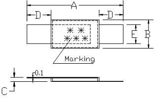
★ Product Dimensions
|
Model
|
A
|
B
|
C
|
D
|
E
|
|||||
|
Min
|
Max
|
Min
|
Max
|
Min
|
Max
|
Min
|
Max
|
Min
|
Max
|
|
|
LR-200
|
20.9
|
23.1
|
4.6
|
5.5
|
0.4
|
1.0
|
3.5
|
6.0
|
3.8
|
4.2
|
|
LR-260
|
20.9
|
23.1
|
4.6
|
5.5
|
0.4
|
1.0
|
3.5
|
6.0
|
3.8
|
4.2
|
|
LR-300
|
24.0
|
27.5
|
6.9
|
7.5
|
0.4
|
1.0
|
4.0
|
7.5
|
4.8
|
5.2
|
|
LR-350
|
24.0
|
27.5
|
6.9
|
7.5
|
0.4
|
1.0
|
4.0
|
7.5
|
4.8
|
5.2
|
|
LR-380
|
24.0
|
27.5
|
6.9
|
7.5
|
0.4
|
1.0
|
4.0
|
7.5
|
4.8
|
5.2
|
|
LR-420
|
24.0
|
27.5
|
9.8
|
10.5
|
0.4
|
1.0
|
4.0
|
7.5
|
4.8
|
5.2
|
|
LR-450
|
24.0
|
27.5
|
9.8
|
10.5
|
0.4
|
1.0
|
4.0
|
7.5
|
4.8
|
5.2
|
|
LR-550
|
24.0
|
27.5
|
9.8
|
10.5
|
0.4
|
1.0
|
4.0
|
7.5
|
4.8
|
5.2
|
|
LR-600
|
27.1
|
29.1
|
13.9
|
14.5
|
0.4
|
1.0
|
4.1
|
5.5
|
5.9
|
6.6
|
|
LR-730
|
27.1
|
29.1
|
13.9
|
14.5
|
0.4
|
1.0
|
4.1
|
5.5
|
5.9
|
6.6
|
|
LR-900
|
45.4
|
47.6
|
7.9
|
8.5
|
0.4
|
1.0
|
4.6
|
6.2
|
5.9
|
6.1
|
|
LR-1410
|
58.0
|
60.0
|
13.4
|
14.0
|
0.4
|
1.0
|
4.2
|
5.8
|
5.9
|
6.1
|
★ Electrical Characteristic
|
Model
|
Ihold
|
Itrip
|
Vmax
|
Imax
|
Pd
|
Itrip
|
Ttrip
|
Rmin
|
Rmax
|
R1max
|
|
(A)
|
(A)
|
(V)
|
(A)
|
(W)
|
Current(A)
|
Time(S)
|
(Ω)
|
(Ω)
|
(Ω)
|
|
|
LR200
|
2.00
|
4.40
|
16
|
100
|
1.60
|
10.0
|
5.0
|
20
|
40
|
80
|
|
LR210
|
2.10
|
4.40
|
16
|
100
|
1.60
|
10.5
|
5.0
|
20
|
35
|
70
|
|
LR260
|
2.60
|
5.20
|
16
|
100
|
1.60
|
13.0
|
5.0
|
15
|
30
|
60
|
|
LR300
|
3.00
|
6.30
|
24
|
100
|
2.40
|
15.0
|
5.0
|
15
|
31
|
62
|
|
LR350
|
3.50
|
7.00
|
24
|
100
|
2.40
|
17.5
|
5.0
|
17
|
31
|
62
|
|
LR380
|
3.80
|
7.60
|
24
|
100
|
2.40
|
19.0
|
5.0
|
13
|
22
|
44
|
|
LR420
|
4.20
|
8.30
|
24
|
100
|
2.00
|
21.0
|
5.0
|
12
|
24
|
48
|
|
LR450
|
4.50
|
9.00
|
20
|
100
|
2.00
|
22.5
|
5.0
|
11
|
20
|
40
|
|
LR550
|
5.50
|
10.50
|
20
|
100
|
2.00
|
27.5
|
5.0
|
9
|
16
|
32
|
|
LR600
|
6.00
|
11.70
|
20
|
100
|
2.80
|
30.0
|
5.0
|
7
|
14
|
28
|
|
LR730
|
7.30
|
14.10
|
20
|
100
|
3.30
|
36.5
|
5.0
|
5
|
12
|
24
|
|
LR900
|
9.00
|
16.70
|
20
|
100
|
3.80
|
45.0
|
5.0
|
6
|
10
|
20
|
|
LR1410
|
14.10
|
26.20
|
20
|
100
|
6.00
|
70.5
|
5.0
|
3
|
5
|
10
|
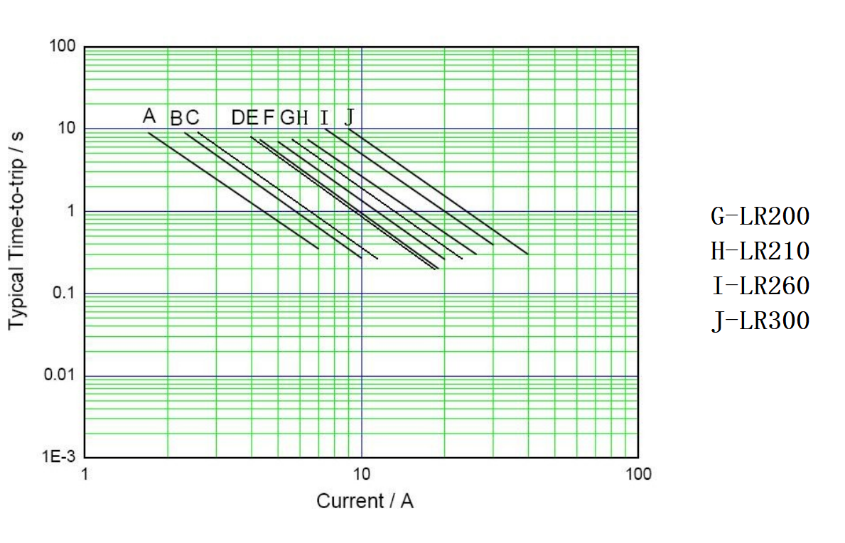
★ Thermal Derating Chart-IH( A)
|
Model
|
Maximum ambient operating temperatures( ℃ )
|
|||||||||||||||||
|
-40
|
-20
|
0
|
25
|
40
|
50
|
60
|
70
|
80
|
85
|
|||||||||
|
LR-200
|
3.1
|
2.8
|
2.5
|
2.0
|
1. 7
|
1.5
|
1.4
|
1.2
|
1.0
|
0.9
|
||||||||
|
LR-260
|
3.8
|
3.4
|
3.1
|
2.6
|
2.2
|
2.0
|
1.9
|
1.7
|
1.4
|
1.3
|
||||||||
|
LR-300
|
5.1
|
4.4
|
3.7
|
3.0
|
2.3
|
1.9
|
1.6
|
1.2
|
0.9
|
0.7
|
||||||||
|
LR-350
|
5.3
|
4.8
|
4.3
|
3.5
|
3.0
|
2.7
|
2.5
|
2.1
|
1.8
|
1.7
|
||||||||
|
LR-380
|
5.4
|
4.9
|
4.4
|
3.8
|
3.3
|
3.0
|
2.8
|
2.5
|
2.3
|
2.1
|
||||||||
|
LR-420
|
6.3
|
5.7
|
5.1
|
4.2
|
3.6
|
3.3
|
3.0
|
2.6
|
2.2
|
2.1
|
||||||||
|
LR-450
|
6.5
|
5.8
|
5.3
|
4.5
|
3.9
|
3.6
|
3.3
|
2.9
|
2.6
|
2.4
|
||||||||
|
LR-550
|
7.6
|
6.9
|
6.2
|
5..5
|
4.7
|
4.3
|
4.0
|
3.6
|
3.2
|
3.0
|
||||||||
|
LR-600
|
8.7
|
7.8
|
7.1
|
6.0
|
5.2
|
4.7
|
4.4
|
3.9
|
3.4
|
3.2
|
||||||||
|
LR-730
|
10.5
|
9.5
|
8.6
|
7.3
|
6.3
|
5.7
|
5.4
|
4.7
|
4.2
|
4.0
|
||||||||
|
LR-900
|
12.7
|
11.4
|
10
|
9.0
|
7.5
|
6.8
|
6.2
|
5.5
|
4.9
|
4.5
|
||||||||
|
LR-1410
|
19.9
|
17.8
|
15.7
|
14.1
|
11.8
|
10.8
|
9.7
|
8.7
|
7.7
|
7.2
|
||||||||

★ Test Procedures And Requirements
|
Test
|
Test Conditions
|
Accept/Reject Criteria
|
|
Resistance
|
In still air @ 25℃
|
Rmin≤R≤Rmax
|
|
Time to Trip
|
Specified current,Vmax,25℃
|
Tmaximum Time to Trip
|
|
Hold Current
|
30min,at IH
|
No trip
|
|
Trip Cycle Life
|
Vmax,Imax,1000cycles
|
No arcing or burning
|
|
Trip Endurance
|
Vmax,24hours
|
No arcing or burning
|
★ Physical Characteristics and Environmental Specifications
Physical Characteristics
| Leadmaterial | 0.125mm nominal hickness,quarter-hardnickel |
| Tape material | Polyester |
Environmental Specifications
|
Test
|
Conditions
|
ResistanceChange
|
|
Passiveaging
|
70℃,1000hours
|
±10%
|
|
Humidityaging
|
85℃/85%RH.7days
|
±5%
|
|
Vibration
|
IL-STD-883C,TestConditionA
|
Nochage
|
★ Electrical Specifications
Ihold=Hold current: maximum current device will not trip in 25℃ still air.
Itrip= Trip current: minimum current device will always trip in 25℃ still air.
Vmax=Maximum voltage device can withstand without damage at rated current(Imax).
Imax=Maximum fault current device can withstand without damage at rated voltage(vmax).
Pdmax= Power dissipated when device is in the tripped state in 25℃ still air environment at rated voltage.
Max Time-to-trip=Maximum time to trip(s) at assigned current.
Rmin=Minimum device resistance prior to tripping at 25℃.
Rmax=Maximum device resistance prior to tripping at 25℃.
R1max=Maximum device resistance one hour after it is tripped at 25℃